ControlPanel
General
When starting the ControlPanel, the model must be operational: battery charged and connected, model and remote control switched on and bound. Servos must be able to move.
The system is automatically detected and all modules are loaded and displayed.
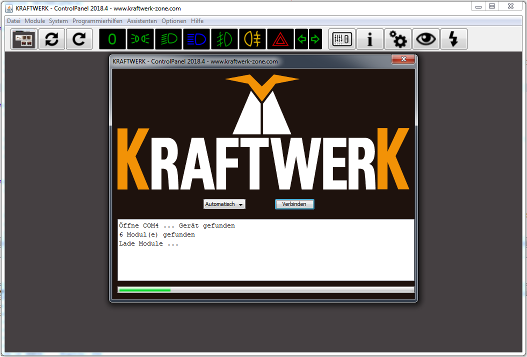
image72.png
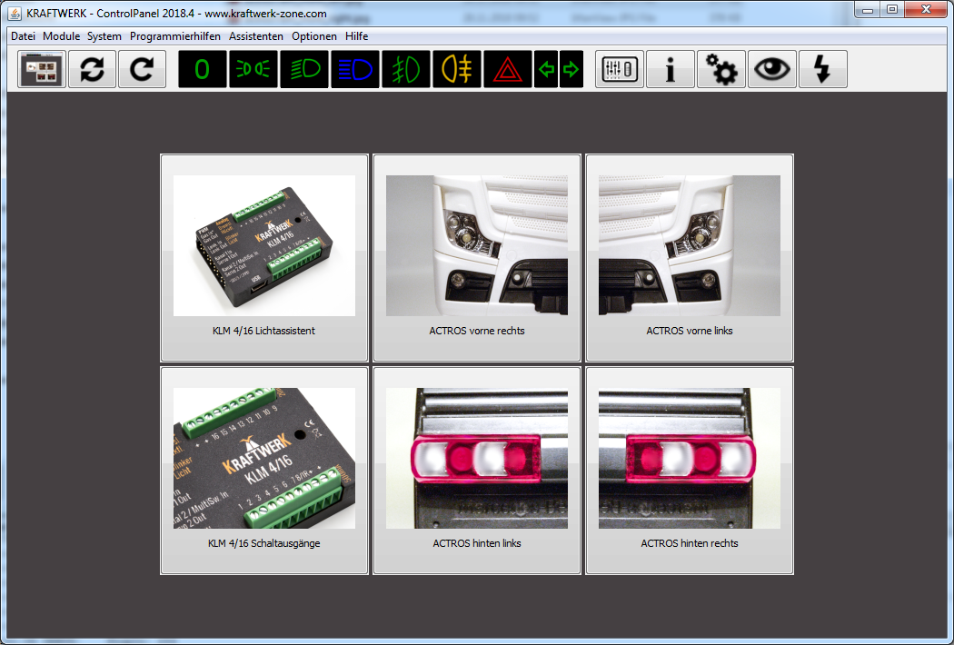
image73.png
Module Overview
By clicking on a module, you reach the output overview. There you can assign names and set on/off speeds. Depending on the function, the parameters vary (see chapter 7 "Functions").
Changes are saved with the floppy disk icon. The question mark shows help texts, the eye switches the output on the model to facilitate assignments.
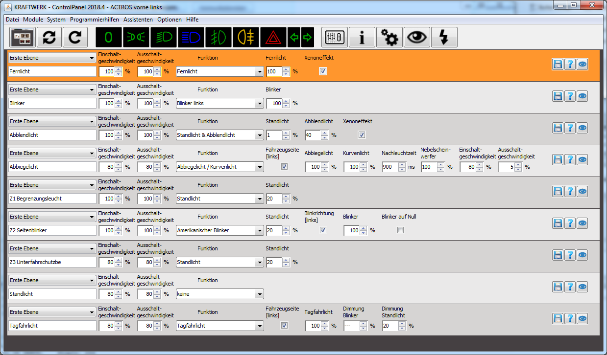
image74.png
Dual Assignment
Each output can be assigned twice. Example:
- First level: parking light & high beam
- Second level: hazard warning lights
The switching between levels can be configured.
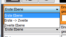
image75.png
to 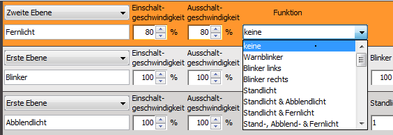
image77.png
Menu
| Function | Description |
|---|---|
| File | Reconnect system, reload module, discard temporary changes, save and open modules. |
| Modules | Display and load all modules. |
| System Settings | Configure basic system behavior. |
| Device Information | Information about modules, software versions, updates, factory settings. |
| System Analysis | Self-test, communication test, find damaged modules. |
| Channel Learning Assistant | Supports learning the channels. |
| Logging | Communication between ControlPanel and system for troubleshooting. |
| Live Data Assistant | Shows real-time data such as stick deflections and switch states. |
| All-Round Light and KnightRider Effect Assistant | Helps with configuration across multiple outputs. |
| Settings | Expert options for advanced settings (use with caution). |
| Info | Information about ControlPanel and error reports. |
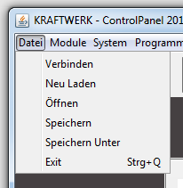
image78.png
Toolbar
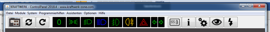
image85.png
- Show main screen
- Reconnect system
- Reload modules
- Lights off / parking light / low beam / high beam / fog lights / rear fog light on/off
- Live data, device information, system settings
- Show live output, open live update
Live Data
Allows real-time insight into stick positions and switch states. Channels can be learned and functions switched on/off.
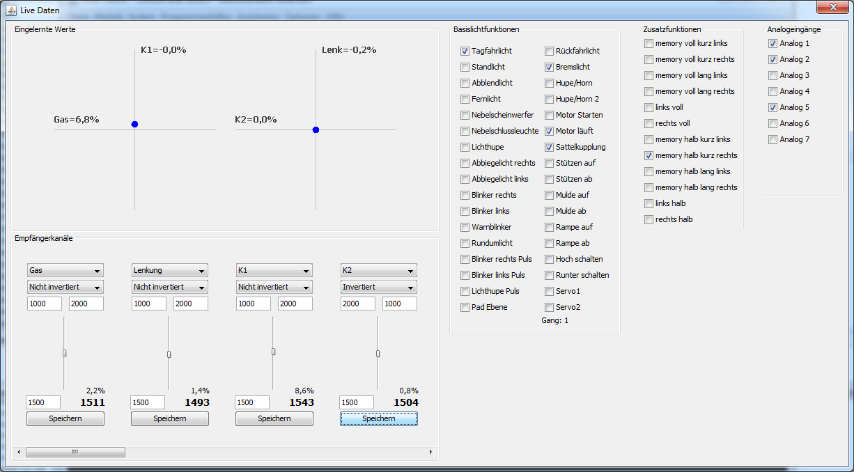
image86.png
| [[IMAGE_078]] | When the channels are correctly learned, the blue dots must follow your stick movements. If you use CPPM, IBUS, or SBUS, the channels must also be correctly assigned. |
| 665544332211 [[IMAGE_079]] | Here all channels are displayed as actually measured. The learning information is not considered here, i.e., the bars can also move downwards even if the stick is moved upwards. 1: A change of channel assignment should only be done if CPPM, IBUS, or SBUS is used. 2-5: These values are set by the learning process. 1000 – 2000 and 1500 center position are the standard values. The values can be adjusted and saved. 6: Scroll right to see the values for the other channels (only relevant for CPPM, IBUS, SBUS) |
| The right side of the live data shows the switch states. Some can be set by clicking. The three function groups basic light functions, additional functions, and analog can be used as switches in the functions, e.g., in the simple switch function. [[IMAGE_080]] [[IMAGE_081]] |
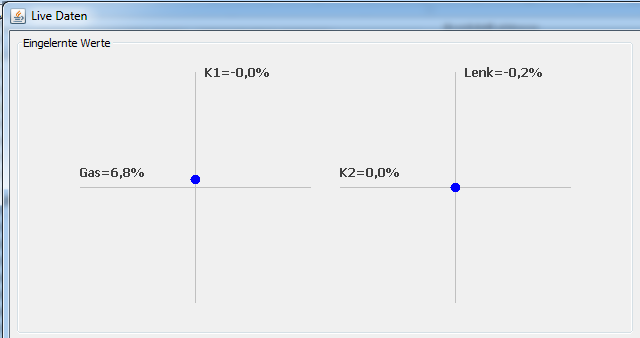
image87.png
The blue dots must follow the stick movements. For CPPM, IBUS, or SBUS, channels must be correctly assigned.
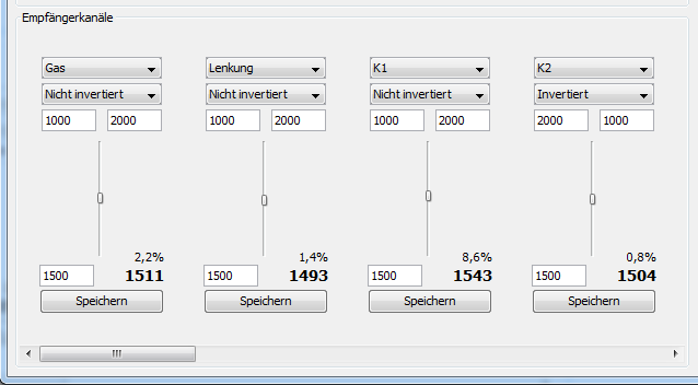
image88.png
The right side shows switch states, which can also be set by clicking. The three function groups basic light, additional functions, and analog can be used as switches.
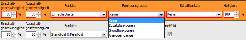
image90.png
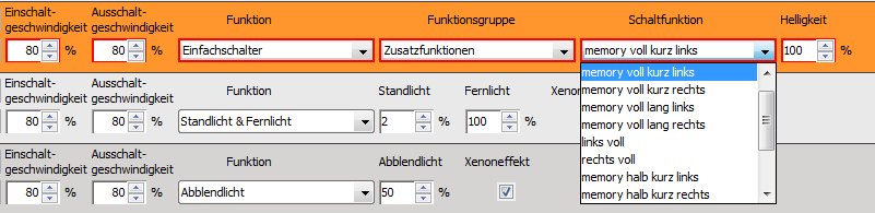
image91.png