Installation General – Determining the Pin Assignment
Theory
The position detection of the control units in most remote controls is done using standard potentiometers that work as classic voltage dividers. The principle is simple:
- Between terminals A and B there is a carbon layer.
- A movable contact (the so-called "wiper") shifts along this layer.
- The voltage measured at the wiper is a portion of the voltage applied between A and B.
Example: If 5 V is applied between A and B and the stick is in the middle, you measure about 2.5 V between A and W as well as between W and B. When the stick moves, the voltages change accordingly.
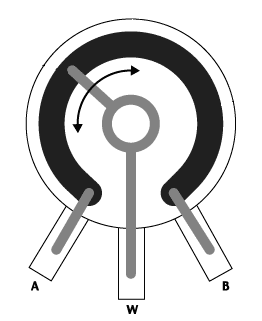
image11.png
Practice – Determining the Pin Assignment
- Turn on the remote control and take a multimeter.
- Avoid short circuits and touching other contacts during the measurement.
- Check if the multimeter test leads are connected correctly (black to COM, red to V).
- If unsure, check the polarity with a battery.
-
Measure the voltages between the pins and note the values:
-
Pin 1 to Pin 2
- Pin 1 to Pin 3
-
Pin 2 to Pin 3
-
The highest measured voltage corresponds to the supply voltage (typically 3 V, 3.3 V, or 5 V).
- The brown wire is connected to the negative pole (ground), the red wire to the positive pole.
- The orange wire is connected to the remaining pin (wiper).
Now press the upper left button on the pad. A servo connected to the corresponding receiver output should move. If the movement is too small, the control range can be adjusted later.
For 3-pin connectors with 2.54 mm pitch, the supplied connector housing can be used. Otherwise, the socket cable can be soldered and the pad plugged in.